Article Text

Abstract
Objectives To compare susceptibility of five different stent platforms with longitudinal stent deformation (LSD) using a clinically relevant bench testing model simulating both short and long malapposed lengths.
Background Recent data suggest that design modifications to the Promus Element stent which led to the Promus Premier stent has reduced susceptibility to LSD. However, susceptibility to LSD at long malapposed lengths has not been tested. Furthermore, the mechanisms behind susceptibility to LSD are as yet unclear.
Methods The Omega, Integrity, Multilink 8, Biomatrixand Promus Premier stent platforms were tested. The Omega, Integrity and Multilink 8 platforms were used in place of their drug-eluting equivalents. 3.5 mm stents were deployed in a stepped tube with the distal portion fixed and the proximal test section exposed. The force required to compress stents by a fixed distance at different exposed lengths was compared. Symmetrical and point loading were used.
Results The Promus Premier was longitudinally as strong as Multilink and Integrity at a short exposed length (4 mm) but weaker, in between Omega and the other platforms, at longer exposed lengths (12 mm). As previously noted, the Omega (Promus Element) platform was significantly weaker than the other stents and Biomatrix was the strongest stent.
Conclusion Susceptibility to LSD varies depending on length of malapposed segment when tested using a clinically relevant model as in this study. The mechanisms behind the susceptibility are likely multifactorial, including connector number, strut thickness, connector alignment and ring orientation but remain to be elucidated.
- longitudinal stent deformation
- coronary artery disease
- percutaneous coronary intervention
This is an Open Access article distributed in accordance with the Creative Commons Attribution Non Commercial (CC BY-NC 4.0) license, which permits others to distribute, remix, adapt, build upon this work non-commercially, and license their derivative works on different terms, provided the original work is properly cited and the use is non-commercial. See: http://creativecommons.org/licenses/by-nc/4.0/
Statistics from Altmetric.com
Key questions
What is already known about this subject?
Susceptibility to longitudinal stent deformation (LSD) varies greatly depending on stent design. However, the factors related to LSD susceptibility are poorly understood. Current bench testing models have limited clinical relevance due to either limited range of test conditions or unrepresentative modelling. More extensive modelling is therefore required.
What does this study add?
The Promus Premier stent was significantly more susceptible to LSD at longer exposure lengths. In addition to connector number, LSD susceptibility is likely affected by ring-to-ring orientation, strut thickness and connector alignment. However, this study is only hypothesis generating and further work is needed to elucidate the mechanisms responsible for LSD susceptibility.
How might this impact on clinical practice?
The Promus Premier stent is likely to be particularly prone to LSD at longer malapposition lengths. Platforms that share design features with the Promus Element and Premier stents are also likely to be prone to LSD. The multiple factors that affect susceptibility to LSD need to be considered in current and future stent designs.
Introduction
A major focus over recent years has been to improve stent deliverability and conformability, using a number of modifications to the stent design, including changes to the stent platform itself. While increasing deliverability and conformability, such design changes may have unexpected outcomes, with susceptibility to longitudinal stent deformation (LSD) being one of them, due to reduced longitudinal strength.1 2 This infrequently reported complication is usually a result of a compressive force localised to one or two contact points on the proximal circumference of a malapposed stent.2 3 LSD of the Promus Element stent (Boston Scientific, Natick, Massachusetts, USA) has been reported in both bench testing and clinical studies.4–6 Results from bench testing models showed that the Promus Element required significantly less force to compress than other contemporary stent platforms. This led to modification of the Promus Element stent by adding extra connectors between the proximal three rings in the Promus Premier stent, while retaining the same ring and connector structure in the rest of the stent, to reduce susceptibility to LSD. However, previous bench models have been very limited in their scope, with models that lack clinical relevance or focus only on connector number or orientation.
Previous bench testing studies have predominantly used symmetrical compression testing of stents, that is, applied uniform force over the entire circumference of the stent, supported from the inside by a mandril. Recently, Ormiston et al have used a more clinically relevant bench testing model of LSD.7 Using this model, they tested the newer Promus Premier stent against other platforms including the Promus Element and reported a significantly improved longitudinal strength in the Promus Premier stent. However, there have been clinical case reports of LSD with the Promus Premier stent.8 In Ormiston’s second paper, they tested the reinforced proximal end of the Promus Premier stent; however, it is uncertain whether under different conditions, for example, longer exposed lengths, the platform would behave differently.7 Furthermore, it is important to characterise the mechanisms leading to LSD, which are as yet unclear, as this will be important in future stent design. In our study, we used a similar model to Ormiston. However, in contrast to the Ormiston study that used a 5 mm exposure length (ie, the length of stent mimicking the malapposition length), we used three clinically relevant exposure lengths: 4, 7m and 12 mm. The longer exposure length is particularly relevant in clinical scenarios such as bifurcation stenting or with a long stent in a tapered vessel prior to postdilation. We looked at the differences between platforms and specifically how the Promus Premier and Element stents compare with other commonly used platforms at the time of this study, particularly at the longer exposure lengths which has as yet not been reported.
Methods
Stent platforms
We compared five platforms: Omega (Boston Scientific), Multilink 8 (Abbott Vascular, Redwood City, California, USA), Integrity (Medtronic, Minneapolis, USA), Biomatrix Flex (Biosensors, Singapore) and Promus Premier (Boston Scientific). The former three bare metal stents were chosen as they are the identical platforms to the drug-eluting Promus and Taxus Element (Boston Scientific), Xience Prime (Abbott Vascular,) and Resolute Integrity (Medtronic) stents, respectively. The Biomatrix Flex and Promus Premier stents do not have bare metal equivalents. We chose 3.5 mm diameter stents for all platforms to avoid testing a mixture of small and large vessel platforms that exist for 3 mm diameter stents depending on the manufacturer. Stent length was greater than 18 mm in all cases. Table 1 shows the stent platform structures and characteristics for the stents used.
Stent platform characteristics
Coronary artery model
Stents were deployed in a coronary artery model in which the stent was embedded into vessel wall in the distal section, and unapposed in the proximal test section. The coronary artery model for point testing consisted of a rigid transparent acrylic tube (inner diameter 5 mm) with a soft silicone tube (inner diameter 3 mm) placed within its distal half creating a lumen with a step in diameter from 3 to 5 mm. The model used for symmetrical testing used larger tubes with a step in diameter from 3 to 7 mm to allow free movement of the rod delivering the compression. The gap between the stent and the outer tube was 0.75 mm in our coronary model. The stent was deployed at nominal pressure across this step resulting in its distal portion being embedded in the silicone tubing and its proximal portion completely unapposed above the step. Compression was therefore limited to the exposed section.
Compression testing protocol
We performed symmetrical and point compression of different exposed lengths of stent and compared the forces required to produce shortening equivalent with that observed in clinical cases of LSD. Three different ‘exposed lengths’ of stent were used (4, 7 and 12 mm) to replicate a range of possible clinical scenarios. A 4 mm diameter rod was used to deliver symmetrical compression to the whole proximal end of the stent. A forked pin was used to deliver point compression (figure 1). The first series of point and symmetric testing were done at 7 mm exposed length. Five repetitions for each stent were performed at each position, compressing each stent by 4 mm (as this was the first series of tests, an additional ≤1 mm compression was carried out to ensure that the required 4 mm compression was obtained). The force necessary for each millimetre compression was recorded.

Compression testing. Diagram showing symmetrical compression with a rod (A), point testing with a fork mid-connector (B) or over connector (C).
The next series of point and symmetrical compression testing were performed at 4 and 12 mm exposed lengths, which were compressed 2.5 and 7 mm, respectively. The force required to compress the platform was measured at 0.5 and 1 mm compression intervals, respectively.
Four repetitions of point and symmetrical compressions were performed. Five repetitions (similar to the 7 mm exposure) could not be performed due to logistical reasons with stent platform availability.
Photographic images
Static images were obtained of the compressed stent platforms using a Nikkon digital camera.
Statistical analysis
For point testing, we first compared over connector and mid-connector compression for each platform. Following this analysis, if no significant difference was to be noted between over connector and mid-connector values, the values were pooled as ‘point loading’ at each exposed length. Platforms were then compared under symmetrical loading and point loading respectively by comparing the force required to compress each platform up to 2.5 mm for 4 mm exposed length, up to 4 mm for 7 mm exposed length and up to 7 mm at 12 mm exposed length. Repetitions were averaged by taking an arithmetic mean force, and by sixth order polynomial least-squares curve fitting. For continuous variables, appropriate parametric (paired t test for paired and independent samples t test for non-paired data, one-way analysis of variance for multiple comparisons with Bonferroni correction) tests were used.
Results
Mid-connector versus over connector and point versus symmetrical testing
At 7 mm exposure, no significant difference was found in the force required to compress a platform by 4 mm between mid-connector (0.439±0.030 N) and over connector (0.426±0.037 N) point compression (p=0.799). Thus, we pooled the mid-connector and over connector measurements and labelled this as ‘point testing’ for subsequent analysis. Symmetrical loading required approximately twice the force as point testing to cause 4 mm displacement (0.771±0.080 vs 0.433±0.024; p≤0.0001) Force–displacement curves for each stent are shown in online supplementary figure S1 .
Supplementary file 1
At 4 mm exposure, no significant difference was found between mid-connector and over connector compression (0.479±0.052 N vs 0.526±0.810; p=0.627). Symmetric testing was then compared against point testing and found to be approximately twice the force required for point testing (1.095±0.108 vs 0.503±0.047 N; p<0.0001).
At 12 mm exposure, no significant difference was found between mid-connector and over connector compression (0.594±0.075 N vs 0.542±0.070 N; p=0.620). The force required to compress the stent using point testing was not significantly lower than that for symmetrical testing at 12 mm exposure (0.568±0.050 N vs 0.676±0.050 N; p=0.135).
Comparison between stents point and symmetrical testing
Seven-millimetre exposure point testing
The Omega stent was significantly weaker than every other stent using point compression (p<0.0001 for each comparison). The Biomatrix stent was significantly stronger than all other stents (p<0.0001 for each comparison). The Promus Premier was not significantly stronger or weaker when compared with the Integrity or Multilink 8 stents (p=0.187 and p>0.999, respectively)
Seven-millimetre exposure symmetrical testing
The Omega stent was significantly weaker than all other stents (vs Integrity p=0.0002; vs Multilink 8 p=0.0001; vs Biomatrix p<0.0001; vs Promus Premier p=0.003), The Biomatrix stent was significantly stronger than all other stents (p<0.0001 for each comparison). The Promus Premier was not significantly stronger or weaker when compared with the Integrity or Multilink 8 stents (p>0.999).
Four-millimetre exposure point testing
The Omega stent was the weakest of all the stents and significantly weaker than the Biomatrix and Integrity stents (p=0.004 and p=0.037, respectively). None of the other comparisons were statistically significant.
Four-millimetre exposure symmetrical testing
The Omega stent was significantly weaker than all other stents except the Multilink 8 stent. The Biomatrix stent was significantly stronger than the Multilink 8, Integrity and the Omega stents but not the Promus Premier stent. The Promus Premier stent was not significantly different to the Integrity, Multilink 8 and as mentioned previously, the Biomatrix stent.
Twelve-millimetre exposure point testing
The Omega stent was significantly weaker than all other stents (p<0.0001) except the Promus Premier (p=0.085). The Biomatrix stent was the strongest of all the stents being significantly stronger than the Promus, Integrity and Omega stents. The Promus Premier stent came out significantly weaker than the Integrity (p=0.030) and Multilink 8 (p<0.0001) stents.
Twelve-millimetre exposure symmetrical testing
The Omega stent was the weakest of all the stents and was significantly weaker than all stents except the Multilink 8 (p=0.060). Although, numerically Biomatrix appeared the strongest stent, there was no significant difference between the force required for symmetrical compression between the Promus Premier, Multilink, Integrity and Biomatrix stents.
Online supplementary figure S2 shows force displacement curves for point and symmetrical loading for each stent at all three exposure lengths. Statistical results of individual comparisons between stents are shown in online supplementary tables 1–6.
Supplementary file 2
Supplementary file 3
Photographic images of compressed stents
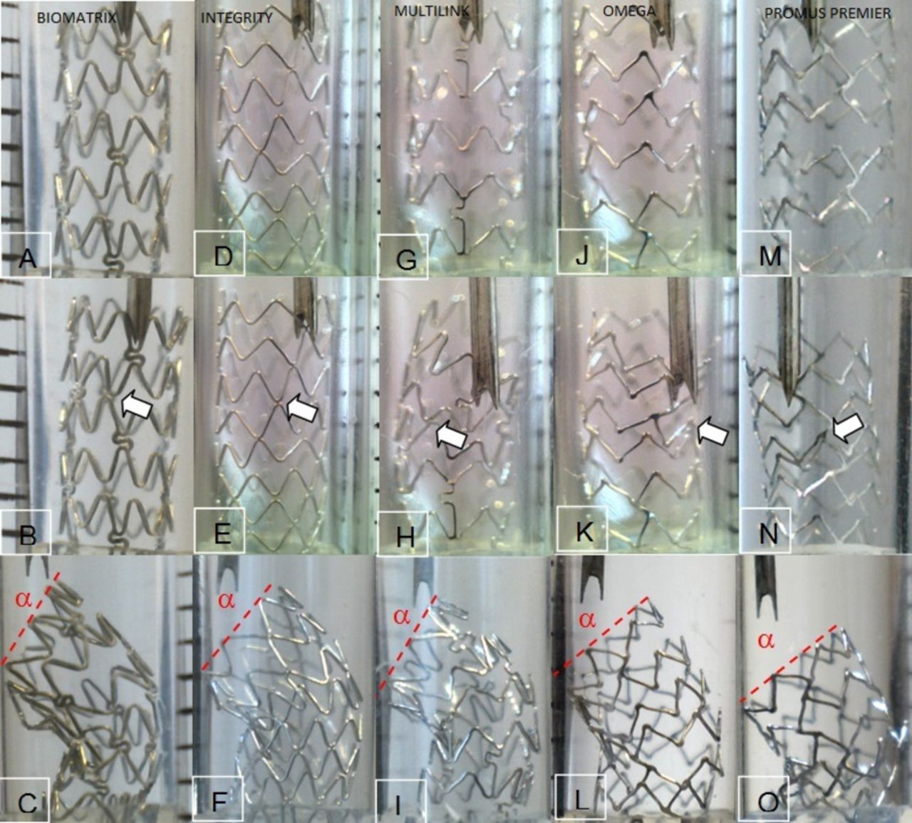
Figure 2 shows each exposed stent prior to point compression, the first ring-to-ring contact and following 4 mm compression. Compared with the other platforms, the proximal three rings of the Premier stent remained intact at 4 mm point compression with the compression occurring below and there was less recoil. Visual inspection of the inlet angle (α) showed that it was steeper for the Biomatrix, Integrity and Multilink stents than the Omega and Premier stents. Angles were assessed by visual inspection only and not measured. Figure 3 shows the Multilink 8, Biomatrix, Integrity and Omega platforms at different phases in the compression testing. The appearances of the stents following point loading closely resemble cases of LSD. Online supplementary figure S3 shows a comparison between an in-phase (Multilink 8) and out-of-phase (Integrity) platforms, showing the various phases of stent distortion during the compressive force. In the Integrity stent, during compression, the rings were in contact within 0.5 mm. This was followed by slippage, with the valley slipping behind the peak on the ring below. For the Multilink 8, an in-phase three connector stent with aligned connectors, ring-to-ring contact occurred only very late. Online supplementary figure S4 shows a comparison between two stents with differing connector alignments. The Multilink 8, with diagonally aligned connectors, was compared with the Omega, with non-aligned connectors. The Multilink 8 resisted compression to a higher force compared with the Omega.
Supplementary file 4
Supplementary file 5

Panels A–C shows a 7 mm exposed Biomatrix stent prior to point compression, the first ring-to-ring contact (0.7 mm compression) and following 4 mm compression. Panels D–F shows the Integrity stent prior to point compression, the first ring-to-ring contact (0.5 mm compression) and following 4 mm compression. Panels G–I shows a 7 mm exposed Multilink stent prior to point compression, the first ring-to-ring contact (3 mm compression) and following 4 mm compression. Panels J–L shows a 7 mm exposed Omega stent prior to point compression, the first ring-to-ring contact (2.5 mm compression) and following 4 mm compression. Panels M–O shows a 7 mm exposed Premier stent prior to point compression, the first ring-to-ring contact (2.5 mm compression) and following 4 mm compression. Arrows indicate the ring-to-ring contacts. The proximal three rings of the Premier stent (O) have remained intact with the compression occurring below, and there is less recoil than the other platforms. Visual inspection of the inlet angle (α) shows it is steeper for the Biomatrix, Integrity and Multilink stents that the Omega and Premier stents.

![[SP1.jpg]](https://openheart.bmj.com/content/openhrt/4/2/e000537/DC1/embed/inline-supplementary-material-1.jpg?download=true)
![[SP2.jpg]](https://openheart.bmj.com/content/openhrt/4/2/e000537/DC2/embed/inline-supplementary-material-2.jpg?download=true)
![[SP4.jpg]](https://openheart.bmj.com/content/openhrt/4/2/e000537/DC4/embed/inline-supplementary-material-4.jpg?download=true)
![[SP5.jpg]](https://openheart.bmj.com/content/openhrt/4/2/e000537/DC5/embed/inline-supplementary-material-5.jpg?download=true)
Panels A–D show a 12 mm exposed Biomatrix stent prior to symmetrical loading (A), at 4 mm (B) and following 7 mm compression in orthogonal views (C,D). Panels E–G show a 7 mm exposed Multilink ML8 (Xience V) stent exposed 7 mm prior to symmetrical loading (E) and at 2 mm (F) and following 4 mm compression (G). Panels H–J show an Omega (Element) stent exposed 4 mm prior to symmetrical loading (H), at 1.5 mm (I) and following 2.5 mm compression (J). Panels K–N show a 12 mm exposed Integrity (Resolute) stent prior to point loading (K), at 4 mm (L) and following 7 mm compression in orthogonal anteroposterior (M) and lateral (N) views. Panels O–Q show a 7 mm exposed Multilink ML8 (Xience V) stent exposed 7 mm prior to point loading (O) and at 2 mm (P) and following 4 mm compression (Q). Panels R–T show an Omega (Element) stent exposed 4 mm prior to point loading (R), at 1.5 mm (S) and following 2.5 mm compression (T). The appearances of the stents following point loading closely resemble cases of longitudinal stent deformation .
Discussion
The Biomatrix stent was the strongest and the Omega platform the weakest in terms of LSD at all exposure lengths tested. At short exposure lengths (4 mm), the Promus Premier was as strong as Multilink and Integrity but it was weaker at longer exposed lengths (12 mm).
Ormiston et al have previously attributed the difference between stents on mandril testing to connector number as one of the factors responsible.5 Recently, a second study by Ormiston et al showed that at 5 mm exposed length the 3 mm Biomatrix Flex was the strongest stent; Omega the weakest stent; and Promus Premier, Integrity, Multilink and Vision had intermediate longitudinal rigidity.7 However, the Promus Premier has the most connectors between the proximal three hoops compared with the other stents studied, implying that these differences are likely multifactorial rather than solely related to connector numbers.
Prabhu et al explained the differences between the Element stent and the other platforms, prior to the advent of the Premier stent, in terms of the angle and positioning of the connectors, with the offset peak-to-peak connector of the Element stent allowing nesting of rings.4 In-phase rings neatly nest into each other without contacting each other until substantial shortening has occurred, whereas out-of-phase rings contact each other very early due to contact between the valley of a ring above and the peak of a ring below (online supplementary figure S3). This difference is seen when the in-phase Multilink, Omega and Premier designs are compared with the out-of-phase Integrity and Biomatrix designs. Examination of the force–displacement graphs showed that each contact added to the force required to compress these stents and that ring-to-ring contact was an important mechanism of longitudinal rigidity for out-of-phase designs. Contrary to Prabhu, our findings suggest that it is not distortion in the Element connector itself but rather the in-phase ring orientation and the non-aligned two-connector design that causes nesting of the rings (rather than the part of the crown (peak or valley) where the connectors joined).
Connector number is well known to influence longitudinal rigidity, with four connectors stronger than two connectors.5 We observed the compound effect of connector number and connector alignment by comparing the in-phase thin strut Multilink stent and Omega stents. Both are in-phase designs with two connectors in the Omega which are non-aligned and three connectors in the Multilink which are aligned. The Multilink stent depends almost entirely on its aligned connectors to resist longitudinal compression with ring-to-ring contact occurring only very late (online supplementary figure S3). As the connectors are aligned, the connector from one ring pushes on the connector from the ring below allowing rigidity to be maintained throughout the stent (online supplementary figure S4). In contrast, the Omega stent structure allows the portion of the ring attached to a connector from the ring above to directly approach the ring below, and the in-phase design allows each ring to nest into each other, offering little resistance to compression (online supplementary figure S4).
It is known that LSD affects predominantly the proximal edge. The Promus Premier stent has a heterogeneous connector distribution. This feature aims to increase its resistance to LSD, while retaining the high conformability, deliverability and fracture resistance of the Element design by not having extra connectors throughout.7 However, our results suggest that although this design modification makes the stent more resistant to compression at shorter exposed length, at longer exposed lengths we found it weaker than all the other platforms, apart from the Omega/Element platform. Clinically, it is likely the Promus Premier stent will be very resistant to LSD at short exposed lengths (eg, ostial stenting of the left anterior descending artery with minimal protrusion into the left main stem), but more susceptible than other platforms at long exposed lengths (such as bifurcation stenting or with a long stent in a tapered vessel prior to postdilation). Interestingly, the pattern of LSD is also likely to be different, with deformation located 3 mm into the stent, due to force transmission from the rigid proximal three rings that are resistant to deformation due to the extra connectors as is evidenced from the still photo images (figure 2). This may positively affect re-entry into a deformed Premier stent.
Strut thickness is also a relevant factor. The Biomatrix stent has non-aligned connectors, but is the strongest stent. Its strength comes in part from its three connectors and out-of-phase rings in a similar way to the Multilink and Integrity stents, respectively, but is stronger than both, because of its greater strut thickness.
LSD is an infrequent but important complication of coronary intervention. However, reducing the susceptibility to LSD is only one of several factors which influence stent design, including more important factors such as radial strength, conformability and deliverability. As such, designing a stent involves a compromise between these various factors. The findings in this paper focus on the multiple factors that might influence stent susceptibility to LSD. Based on our findings and correlating these with the structure of the stent platforms (table 1), we propose four factors: ring alignment (in or out of phase), connector number and heterogeneity in connector number within stent, strut rigidity/thickness and connector alignment. However, these are only postulations and not definitive conclusions, considering the limited number of stents tested. Furthermore, anticipated length of exposure of a stent that could be susceptible to LSD could have a bearing on the choice of stent, tailored to the procedure. Newer, more contemporary stents in the market include the Synergy (Boston Scientific) stent. The Synergy stent platform is based on modifications of the Promus Element platform to address, among other factors, longitudinal strength.9 The design has incorporated a number of the factors discussed above, including additional proximal and distal connectors, altered angle of alignment of the connectors, altered radius of the ring peaks and thinner struts, in an attempt to increase longitudinal strength and deliverability. It will be interesting to see what impact this has on LSD incidence with this stent in clinical practice.
Limitations
The current study is limited in terms of number of stent platforms tested and the conclusions drawn are only based on the stent platforms studied. Thus, the results can be considered to be at most hypothesis generating. The deformation secondary to point loading in our model involved two components, shortening along the longitudinal axis of the stent and tilting/bending. The degree of tilt (angle, α) was less for the Element and Premier stents, meaning that deformation was predominantly shortening rather than tilting. If the gap between the stent and the outer tube had been less than the 0.75 mm in our coronary model, tilting would have been more restricted and a greater difference between these stents and the other platforms may have been observed. Clinically, the gap between a stent and the vessel wall prior to postdilation is likely to be less than 0.75 mm at midvessel locations, but could be at least 0.75 mm ostially and in the left main stem. The larger 1.75 mm gap in the symmetrical testing model allowed considerable lateral movement, and again greater differences between the platforms may have been observed if this had been reduced.
Conclusion
The findings of this paper are hypothesis generating and based on a comparative study on five stent platforms only. We have, for the first time, used a clinically relevant bench model of compression testing at three different exposure lengths. The study suggests several observations that might be related to the susceptibility of stent platforms to LSD. More importantly, we have highlighted our lack of clear understanding of the exact factors which increase susceptibility to LSD. Furthermore, stent design is complex and LSD is only one of several factors, some more important than LSD, that influence stent design. Until the time when stents will be resistant to LSD, no alternative to a judicious interventional technique exists. The advent of a clinically relevant model, as used in this study, and the multifactorial susceptibility to LSD suggested, certainly warrant further studies using a larger range of more contemporary platforms to clearly elucidate the factors behind the susceptibility to LSD.
Footnotes
Contributors All authors have contributed significantly to the design, conduct and/or manuscript preparation for this study.
Funding This study was performed with financial and / or materials support from Boston Scientific (Minneapolis, USA), Abbott Vascular (California, USA), Medtronic (Minneapolis, USA) and Biosensors (Singapore).
Competing interests None declared.
Provenance and peer review Not commissioned; externally peer reviewed.